Tremolo
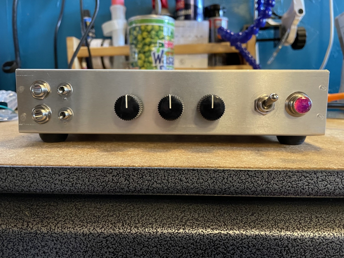
My pandemic staycation project: a Rick-Tone Trem-O-Drive for my Champ, Airline, and Rickenbacker single-ended amps.
I work in an essential industry (although the essential-ness of the work I do is questionable), so unlike most of the planet, I’ve been going into the office every day during this pandemic. I also hadn’t had a vacation in two years. I’m burnt out.
With everything shut down, there is no where to really go, and to simply not be at work seemed like a really sad way to spend a vacation, so I came up with a project!
A few months back, I stumbled upon a Redditor who hipped me to the Rick-Tone Trem-O-Drive—a tremolo and overdrive circuit that uses a single 12AX7, and a simple voltage doubler power supply. Rick Campbell is an Oregon-based amp tech/builder behind the circuit. He generously shares some of his designs on his website. This project appealed to me as it is inexpensive, and would make the perfect compliment to my Fender Champ, Airline 9022A, and Rickenbacker M-8 amps. Tremolo is my favorite effect, and none of my guitar amps have it build in.
I wanted to try my hand at laying out a point to point wired circuit, so I opted for a head unit design to give myself plenty of space. I fix plenty of cramped circuits, and I figured building one from scratch might pose a bit of a challenge. I wasn’t wrong!
Rick provides a great schematic on his website, and two rudimentary (by design) layout diagrams. They simply show you how to wire up the components, but leave the actual layout up to you so that you can build it into whatever enclosure you like.
I spent considerable time mocking up my layout in Adobe Illustrator, pulling measurements for parts from manufactures websites and various online stores.
Most of my components arrived within two or three days (AES shipping is incredibly fast in my area). The chassis and transformers took a bit longer to arrive. While I was waiting, I built a 3-D mockup of the chassis using a cardboard box. I cut holes for the pots, switches and jacks, and taped down terminal strips to get an idea of how realistic my Illustrator mock up actually was.
You can find photos of other Trem-O-Drive builds on the web. A common convention for them is to mount the 12AX7 sideways inside the chassis on an L-shaped bracket. I thought this made for an elegant, compact enclosure, so I fabricated a bracket out of a sheet of aluminum I had on hand.
One thing I couldn’t find measurements for online were the Orange Drop capacitors I chose. It turns out I grossly underestimated the sizes of the .22µF and .047µF caps. If I do another one of these builds, I’ll likely opt for some Mallory axial lead caps in these positions instead.
It took considerable nudging to get things to fit elegantly inside of my cardboard chassis. Once I felt pretty good about it, I took measurements, and laid out my drill templates in Illustrator.
When my other order finally arrived, I placed the transformers, and terminal strips inside the aluminum chassis to see if there were any surprises. What I didn’t account for in the cardboard mock up was the rim of the chassis overlapping the interior by about a centimeter. This would make soldering and bolting down the components more difficult than I anticipated.
I printed and taped up my drill templates. When designing your templates, it’s important to take into account that you will be drilling the chassis from the outside in. Because you will likely take measurements from your interior components from the inside, you will need to reverse your drilling template that gets taped to the outside.
Once all the holes were drilled and filed smooth, I installed the pots, switches, jacks, transformers and tube socket. The rim of the chassis did impede the installation of the transformers a bit. I figured it would be easier to solder as many components as possible to their respective terminal strips outside of the chassis, so I screwed them to a scrap piece of 2x4 to give me a solid base to work from. This really made it easy to nail the intricate layout I came up with for the power supply.
I’m particularly proud of the power supply. I managed to stack everything onto a single 7-lug terminal strip, making use of every lug.
Once the power supply terminal strip was bolted in place, connecting the transformer terminals and B+ output proved to be a little difficult. It’s also a bit difficult to trace the circuit by eye on the single terminal strip. Not unlike programming, there is an art to achieving a balance of compactness, access, and readability.
I took this to heart as I soldered up the terminal strip for the oscillator circuit. I made sure to keep the smaller components at the top, and the larger components off to one side. This made the circuit much easier to read, and the wire connections much easier to solder.
The next issue I ran into was the tube socket. Tubes require clearance to pull in and out. When your tube is mounted sideways inside of your chassis, this space needs to be accounted for. Fortunately, I planned for this, but that room had to come from somewhere, and that somewhere is also the home of two 1/4” jacks, two SPST switches, and a 5-lug terminal strip.
While this cramped-ness does allow for short signal lead runs, accessing some of the terminals was a bit difficult. I also kind of over-built this thing using 20 AWG cloth-covered, solid-core wire. It helped to start from the bottom up, soldering components that would be obscured by other components first.
This foresight paid off. While I did have some difficulty here and there, it wasn’t anything I wasn’t used to dealing with. The only concession I had to make was for a 2.2M resistor. I couldn’t find one, so I wired a 2M and 200k in series. It’s not ideal, but I was able to arrange everything evenly around the tube socket.
With all the components in place, I traced the entire circuit against the schematic, testing all my ground connections with a multimeter. Once everything checked out, it was time for the moment of truth.
I fired it up slowly on a variac, which I have plugged into a current limiter. I started to see the pilot light come on, but once I got up to about 80 volts, the current limiter lit up.
I shut everything down, unplugged, and drained the filter caps. I began looking for possible shorts to ground. With a cramped design, it’s easy for things to be obscured. I looked for stray leads I may have forgotten to trim. Sure enough, there was a lead poking out of pin 7 I missed. It was incredibly hard to see, and even harder to get my cutters around. It’s at this point I decided that mounting tubes sideways inside a chassis like this is just not a good idea.
I plugged back in, slowly dialed up the variac, keeping my eye on the current draw, and once I hit 80 volts, the pilot light blew. This time, though, the current limiter didn’t light up.
I powered down, unplugged, and drained the filter caps. Then I thought for a while.
The bulb blew. Maybe I accidentally ordered a 5.3 VAC pilot light receptacle (my unit uses a 110–125 VAC receptacle). I checked my order. Nope, I ordered the right part. I looked up the bulb. It requires a 20K current limiting resistor that I didn’t include in my build. That’s probably the cause of the bulb blowing, but is this the only thing going on? The current limiter didn’t light up the second time.
I placed an order for a few more bulbs and some other miscellaneous items, and took the pilot light out of the circuit to do some more testing. I measured the B+ coming out of the power supply, and fired it up a third time. The meter read about 220v, but I got nothing else. No runaway current, no sound, no filaments. Aha!
I measured the voltage going into the filaments and couldn’t quite get a solid reading on either one. It ranged from 0 to 7 volts AC. The secondaries are wound for 12.9. Did I blow one or both of the transformers with that original short? Wouldn’t the current limiter or fuse have prevented that?
I decided to pull the transformers to test them and instantly found that one of the wires connecting the secondaries to the filaments had broken off at the terminal strip. Boom!
My bulb order had arrived the previous day, which contained some three-lug terminal strips. I swapped out the five lug I was using at this junction and redid the connection. I added a 20k resistor to the positive lug on the pilot light, then fired it up again.
Pilot: check. Filaments: check. Sweet tremolo? Check!
Wow! The gain stage in this thing really perked up my Champ! You can really dial it in, too. The tremolo is huge and can completely saturate the signal. Remember, your whole signal goes through it.
I think the tremolo could be slowed down a bit more. The lower third of the speed knob doesn’t really have much of an effect. I’ll try increasing the value of one of the oscillation capacitors and see where that gets me. I’m also getting some thumping at higher gain stages. I think re-routing the wire that feeds the grid of the oscillation triode might fix that.
All in all, I’m really happy with this unit. It sounds great, and I had so much fun building it. I learned so much in the process. I kind of want another go at it. I think I could really nail down a good design.
A full album of images is avaiable on Flickr. It includes additional photos and annotations. If you would like to try your hand at building this version, you can download my wiring diagram, drill templates, and parts list (982k PDF).
If you would like me to build you one, get it touch!