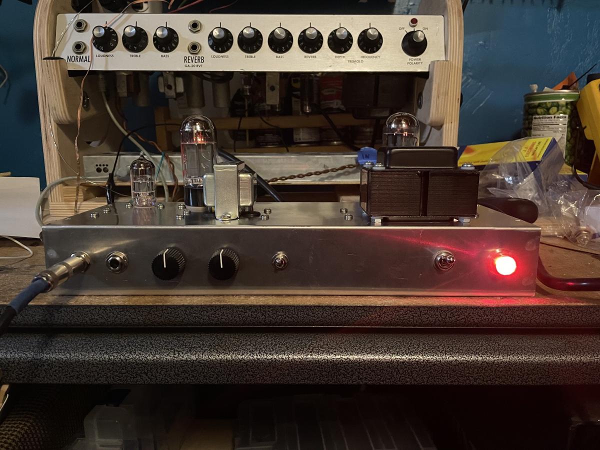
It’s alive! First power up on Feburary 14, 2023. Behind this you can see the Gibson GA-20 I have been overhauling for the past few months. My amp is not as messy.
I Built A Guitar Amplifier From Scratch
I’ve been studying the art of tube amplifier design for about ten years now, and actually repairing them for about five. I love analizing schematics, pouring over the inside of an amp chassis, and studying the layout choices made by the designer. It was only a matter of time before I took a crack at it myself. That time finally came.
Most enthusiasts will recommend a Fender Tweed Champ kit for your first build. There are a lot of gotchas involved with amp building—little details that are easy to miss, layout mistakes that can cause horrible noises, and lethal voltages to contend with. It’s best to with something simple that has clear, step by step instructions, then work your way up from there.
While I whole-heartedly agree with this sentiment, I do feel very comfortable inside of a guitar amp. I have repaired so many at this point that I have formed some strong opinions about the way a circuit should be laid out. A kit wasn’t really going to scratch my itch.
From my pedal builds, I do understand the importance of starting simple and getting through the entire process before tackling something more complex (like the bass amp I really want to build). Because I was also going to be doing a custom layout from scratch, I chose a slightly more complex circuit to base my design on than the Tweed Champ: the Tweed Princeton.
I’m very familiar with this circuit, and I didn’t stray very far from the original, aside from adding a switch to the negative feedback, and another to the 4Ω and 8Ω windings of the output transformer. The main thing I wanted to experiment with here was layout. That isn’t something you can learn from a schematic. Magnetic fields interact, wires cross, things oscillate, components get hot… These are the types of decisions that can really make or break your instrument in the end.
Most single-ended, low-wattage amplifiers are combos. I actually have three of them, and I don’t really consider myself a guitar player. I wanted something I could experiment with, something that would be easy to open up and swap components out, and something that would allow me audition speakers. I wanted a head unit. This also allowed me to choose the very un-Fender-like option of orienting the tubes and transformers on top. Hey, it’s much better for dissipating heat, and easier to change tubes!

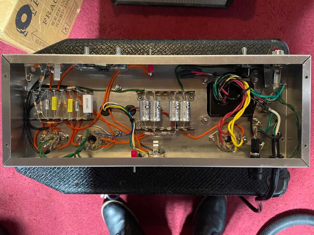
Interior view of the (almost) final chassis. Can you spot the two errors? I wish I had when I shot this photo.
I’m a fan of point-to-point wiring, but that can make swapping out components difficult. Eyelet boards feel cheep to me, and turret boards just feel a little too pretentious for my style, so I went with terminal strips. I like them because you can make all your wire connections below, while keeping terminals up top clear for the components. Its much easier to swap out components this way. You do have to drill a shit-ton of holes, though.
Even though I chose a tubes-on-top design, I prefer the control panel layout of Fender’s brown, black, and silver-face amps, with the inputs and controls to the left, and power switch on the right. This was a really good exercise for my brain. All Fender amps are laid out in the opposite orientation from my design (as are nearly all commercial amplifiers from the 60s and 70s). Not only did I have to reverse the orientation of the power supply, preamp and output sections, I also had to invert the wiring of the controls to keep them in the proper order, and switching in the right direction!
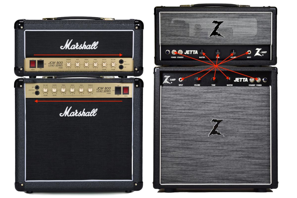
As a user interface/user experience designer, I have always been bothered by builders like Marshall and Dr. Z, who just flip the chassis over for the head versions of their combo amps. This reverses the orientation of the controls between versions of the same amp! It also highlights yet another example (there are many) of Leo Fender’s genius. Fender head units used the same tubes-on-the-bottom layout as their combo amps do. As a result, the control panels aren’t only consistent between head and combo versions of the same amp, they are consistent across the entire product line.

Above are examples of both the head and combo versions of the Marshal JCM 800 Lead Series and Dr. Z Jetta. From a manufacturing standpoint, it’s a no-brainer to use the exact same chassis for the head and combo versions of your amp, and just print a different control panel plate. From an UX standpoint, it’s a brain hurter, but I probably think about this stuff too much.
Fender Tweed amps appear to be the exception to this rule. They were designed with the assumption that the player would stand behind them (that’s why the control panels appear upside down when you look down at them). If you do this, the controls are inverse to the modern Fender layout¹. As it turns out, this is not how players ended up using them. When Leo redesigned the amps to have front-facing control panels in the 1960s, he kept the same internal layout players were already accustomed to from this angle, and just reversed the orientation of the control panel markings.
From an amp building standpoint, it makes little practical (or financial) sense to invert an amp’s architecture just to maintain the same control panel layout for both the combo and head versions. Not only does it require extra design, tooling and inventory, it’s a total mind-fucker! From a usability standpoint, it makes all the sense in the world. Control panels should be consistent across the entire product line. Stages can be dark. Backlines are common. A player needs all the help they can get during a performance. Don’t make me think!
Mind-fuckers aside, the real challenge of this build was cutting the hole for the power transformer. This is one of those operations you don’t run into when repairing amplifiers (at least it shouldn’t be!). I have some experience drilling chassis from my pedal builds, and the tremolo I built a few years ago. I have zero experience cutting rounded rectangles into aluminum boxes, however. It was difficult to get proper measurements for the location of the pilot holes, and even more difficult to get the angle grinder attachment on my Dremel to behave. It’s not pretty, but it is only visible from the inside.
The rest of the build went great and was really fast (if you don’t factor in the layout). I think it took me about eight hours from drilling the chassis to firing it up for the first time. I have been told that it is unreasonable to expect an error-free build your first time around, and I had two! Thankfully, this is where my repair experience paid off.
After making significant repairs, significant changes, or firing up a newly-built tube amp for the first time, it’s best to do so without the tubes installed and check voltages at all the key points around the circuit, like plate connections, filliments, etc. This is how I realized I had forgotten to connect the first two filter stages. I was going to just leave a long lead on one of the filter caps, and use that to connect it to the next terminal over. I decided against that for some reason and made a mental note to my future self to jumper the connection after installing the caps. Which I promptly forgot to do.
The other thing I found was that the 6V heater wires were only conducting 2.6 volts. This is because I accidentally wired the center tap to the heaters to the pilot light instead of the other heater lead. The label on the transformer was a little difficult to decipher. It was much more clear on the tech sheet.
After those changes were made, I put the tubes in and fired it up for real. Success! That was a really good feeling. I checked the bias at this point and it was way too hot. I think plate dissipation was around 17 watts, which is way too high for a 6V6. The sound was pretty harsh and brittle, too. I swapped out the 470Ω cathode resistor for a 1k, and that brought it down to 11 watts. It sounds great! And it sounds really great through my tube tremolo box!
I’ll be passing it around to my guitar player friends to see what they think, and hopefully talk one of them into building a cabinet for it. I’m also looking forward to hooking it up to the speakers in my other combo amps to see how it compares with them.
I think I might be ready to take on that bass amp now.
- The internal layout of a Tweed Fender amp is the same as any other. It’s just that the orientation of the silkscreen on the front is upside down when looking at it from the front.
- Not to diminish kit-building. That sounds very fun too, and you should totally try it!